
Module is available as a DIY project only.
This Module is currently available.
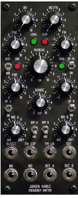
Jurgen Haible Frequency Shifter
JH. FS-1A Frequency Shifter
Updated Version of my FS-1 Frequency Shifter, complete with PCBs.
About 10 years ago I started to build a frequency shifter with the goal to have similar sound quality as the Moog / Bode frequency shifter.
I built this on Veroboard, and I was very pleased with the results.
I've chosen a slightly different approach than the famous Moog / Bode model: Instead of using a beat-frequency oscillator, I implemented a linear and exponential-controlled Quadrature-Thru-Zero VCO directly. This covers the whole audio range, and (anlike the Moog / Bode) goes down far into the sub-audio range, such that you can run it with something like 1 cycle in 10 seconds, for slow "Barberpole Phasing".
Also, I've chosen a different approach for the noise reduction. Every Frequency shifter has to battle carrier bleed-thru. In the new version, I have implemented a second-order trimming which, beyond nulling the carrier in the output, also allows to suppress the quadratic term, which means cancelling the bleed-thru at twice the carrier frequency. Even with so much effort going into the carrier suppression, you want complete silence at the output when no input signal is present. Moog used a "Squelch" circuit for this, which is basically a noise gate, and needs manual adjustment of the threshold, depending on level and nature of the input signal. I am using a special Compander / Downward-Expander system, similar to the one found in the Roland VP330 Vocoder Plus (All opamps and OTAs, NE570 etc.!), slightly changed to fit the needs of a frequency shifter.
Now that I've started designing PCBs (Printed Circuit Boards), and quite flattered by the success of my Tau Phaser PCB project, I decided the Frequency Shifter would be the next in line.
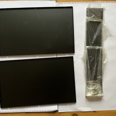
The whole circuit fits on two 160mm x 100mm sized boards:
Board 1 contains the Quadrature-Thru-Zero-VCO, the Ring Modulators, Summing Amps and Compander Circuit.
Board 2 contains the Dome Filter, a Microphone Preamp, an extra 6-pole All Pass Filter for Barberpole Phasing, an Inverter for CV inversion, a Power Supply that only needs a transformer and fuses to be connected, as well as MOTM and Synthesizers.com system connectors for direct +/-15V power supply.
pcb's available at: http://randomsource.net/haible/vintage


 Jurgen Faible Frequency Shifter JH. FS1A