
Module is available as a DIY project only.
This Module is a prototype or in a concept phase.
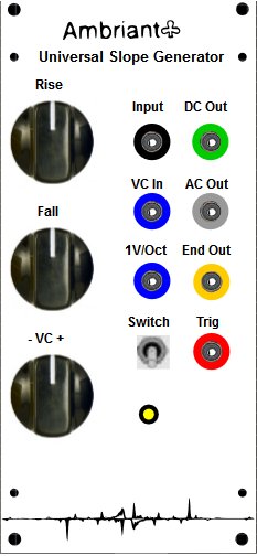
CGS114
Single unit version of the (dual) DUSG. Based on the Ken Stone schematic. The DSG can be used as a simple envelope generator, a low frequency oscillator, pulse generator, or in a variety of other applications. As an envelope generator, the unit can be triggered in two different ways:
Connect a trigger pulse to the TRIG IN jack. When a pulse is applied here, an envelope defined by the RISE and FALL knobs will be produced which goes from 0 to +5 volts. If a second trigger is received before the envelope has finished, it will not re-initiate the envelope.
Using a pulse train into this input, the DSG can be used as a frequency divider, or sub-harmonic generator. A waveshape and a pulse from the END jack will, be produced for each pulse applied to the TRIG IN jack as long as the total envelope time is thorter than the pulse period. If the envelope time is slightly longer than the pulse period, then the DSG will only be triggered on alternate pulses, producing a division of two. If the envelope is slightly longer than two pulse periods, then it will only be triggered on every third pulse, producing a division by three, and so on.
With a gate signal into the IN jack, an envelope will be produced which begins to rise at a rate set by the RISE knob to a level equal to the gate level. The level will remain at this level as long as the gate is present: an envelope with sustain. When the gate level drops back to zero at its end, the envelope will fall at the rate set by the FALL knob. If the gate level rises before the end of the FALL cycle, the output will rise again, rising toward the gate level, at a rate set by the RATE knob. Multiple gate signals will re-initiate the envelope, even if the envelope has not completed its cycle back to zero volts.
A positive signal applied to the IN jack will always over-ride any trigger at the TRIG IN jack.
The DSG can be used as a slew limiting processor to change discrete voltage steps into gliding voltages (portamento). Voltages from a keyboard, sequencer, or other sources can be applied to the IN jack, and the RISE and FALL knobs will now determine the rate of glide in the positive and negative direction, independently.
The slopes from the DSG are linear (equal voltages per unit of time), but they can be altered using feedback. If the OUTPUT is patched to the VC IN jack, then the slope can be given an exponential or a logarithmic shape determined by the amount of feedback set by the processing knob. Since both the RISE and FALL can be switched to be controlled separately or together, the slope of either or both can be shaped using this technique. This is useful for producing slow, gradual amplitude changes with the Equal Power VCA modules.
If the TRIG IN jack is connected to the TRIG OUT jack, the DSG will oscillate with a waveform and frequency set by the RISE and FALL knobs. A series of pulses will appear at the TRIG OUT jack, and the duty cycle (the time the pulse is high compared to when it is low in each cycle) is set by the RISE and FALL knobs. The FALL knob determine how long the pulse is low. When the DSG is in the RISE part of the cycle or when the output is zero or less, the output of the TRIG OUT will be high. In some applications, a pulse with a very long duty cycle will cause erratic triggering in other modules. If such a symptom occurs, try increasing the FALL time and decreasing the RISE time to get the same pulse rate.
The DSG may be used as a positive peak follower by setting the RISE time to minimum (full CW) and applying an audio signal to the IN jack. Adjust the FALL knob for a compromise between response time and the best filtering of the audio component at the DSG output. If the FALL time is turned to minimum, and the RISE knob adjusted for optimum response time and filtering, then the unit will function as an envelope, follower-producing a negative envelope corresponding to the negative peaks ofthe input audio signal.


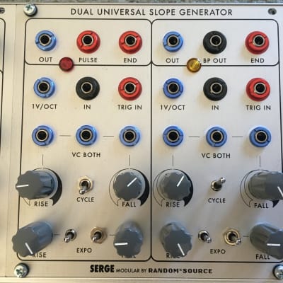 Random Source Serge Dual Universal
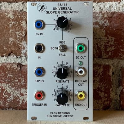 Elby Designs ES114 Universal Slope
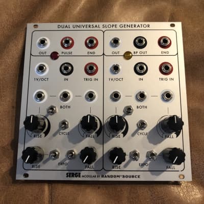 Random Source Serge Dual Universal
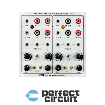 Random Source Serge Dual Universal
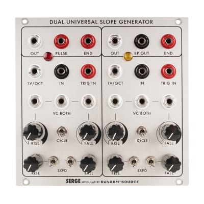 Random Source Serge DUSG Dual Universal
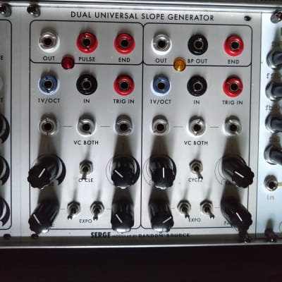 Serge by Random Source Serge Dual