

This Module is currently available.
Stereo Multimode Filter
Module A-121s is a dual multimode filter which can be used for stereo applications as well as for parallel or serial organized dual mono filters. The core is a 12dB multimode filter identical to the modules A-121-2 and A-121-3. The selection of the filter type is continuously from lowpass via notch and highpass to bandpass. We attached great importance to the usability of the manual controls and CV inputs for both stereo and dual mono applications. For the filter parameters frequency (F), resonance (Q) and type (T) common controls and CV inputs as well as single controls and CV inputs are available. For the filter frequency in addition a manual control and CV input for the filter spread (frequency difference or delta F) is available.
Controls:
◉ F: master frequency control for both filters (large knob)
◉ Type 1 / Type 2: filter type panning/morphing L-N-H-B
◉ Link to 1: Toggle switch so that Type 1 also controls type of filter 2 (i.e. simultaneous filter type control for both filters)
◉ SFM1 / SFM2: Single Frequency Modulation controls (polarizers), connected to the corresponding sockets SFM1/SFM2 (socket SFM1 is normalled to a fixed positive voltage, SFM2 is normalled to SFM1, that way the controls SFM1/SFM2 work as frequency controls for each filter provided that no modulation signals are patched to the SFM1/SFM2 sockets)
◉ CFM: common frequency control, controls two VC-polarizers which process the signals connected to the two sockets CFM1/CFM2, CFM2 is normalled to CFM1, that way also the same modulation signal (e.g. an envelope generator) can be used for both filters and the level controlled simultaneously by the CFM control
◉ Delta F: controls the difference between the frequencies of the two filters manually (frequency "spread"), at center position the frequencies are the same
◉ Delta FM: controls the level of the Delta FM signal (socket), which allows to control the spread between the frequencies also by an external control voltage (e.g. by an LFO or ADSR)
◉ Q: controls the resonance of both filters simultaneously
◉ Level 1 / Level 2: attenuators for the two audio inputs
◉ QM/TM1, QM/TM2: attenuators for the modulation inputs QM/TM1 and QM/TM2
Sockets:
⦿ In1 / In2: audio inputs (In2 is normalled to In1)
⦿ Out1 / Out2: audio outputs
⦿ F: common frequency control input for both filters (~ 1V/oct)
⦿ Delta FM: Control voltage for frequency spread, processed by the polarizer Delta FM
⦿ SFM1 / SFM2: single frequency modulation inputs, processed by the polarizers SFM1 and SFM2, SFM1 is normalled to a fixed positive voltage, SFM2 is normalled to SFM1#
⦿ CFM1 / CFM2: common frequency modulation inputs, processed by the two voltage controlled polarizers controlled by CFM knob, CFM2 is normalled to CFM1
⦿ QM/TM1, QM/TM2: the addressing of these sockets/attenuators is defined by internal jumpers. QM means Q modulation (i.e. resonance modulation), TM means filter type modulation (QM1 = resonance modulation filter 1, QM2 = resonance modulation filter 2, TM1 = filter type modulation filter 1, TM2 = filter type modulation filter 2), socket QM/TM1 is normalled to a fixed positive voltage, QM/TM2 is normalled to QM/TM1
Applications:
Stereo filter: two different audio signals are connected to the audio inputs. At the outputs appear the filtered signals. The filterings depend upon the positions of the manual controls and the applied control voltages.
Serial mono filter: the mono signal is applied to audio input 1. Audio output 1 is connected to audio input 2. The filtered mono signal appears at audio output 2. One has to pay attention that the filter parameters are set in a way so that a signal will appear at the output. If for example a lowpass and a highpass are daisy chained the frequency of the lowpass has to be higher than the frequency of the highpass. Otherwise no signal will appear at the output.
Parallel mono filter: the audio signal is fed to both audio inputs (e.g. via the normalled sockets In1>In2). By means of a mixer module the audio outputs 1 and 2 are mixed.
17 Users are observing this


These merchants probably sell this module. Huh?

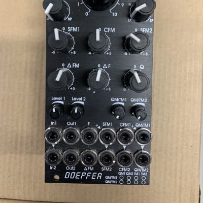 Doepfer A-121s Stereo Multimode Filter
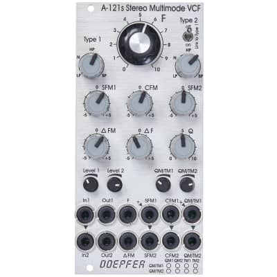 Doepfer A-121s Stereo Multimode Filter
 Doepfer A-121s Stereo Multimode Filter
 Doepfer A-121s Stereo Multimode Filter
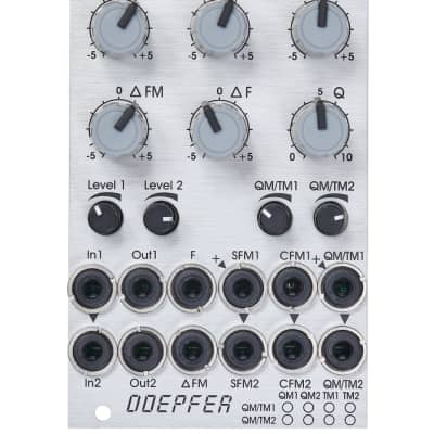 Doepfer A-121s
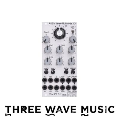 Doepfer A-121s Stereo Multimode Filter -