
This Module is currently available.
Phase Locked Loop
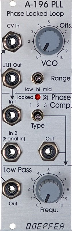
Module A-196 contains a so-called phase locked loop (PLL). A PLL consists of three parts: voltage-controlled oscillator (VCO), phase comparator (PC), and low-pass filter (LPF). All parts are normally connected to form a closed-loop frequency-feedback system.
This is how a PLL works: The output of the internal VCO (linear CV control, rectangle output) is compared with an external signal (e.g. the rectangle output of a A-110 VCO) in the so-called phase comparator (PC). The output of the phase comparator is a digital signal (low/high/tristate) that indicates if the frequency resp. phase difference of the two input signals is negative, zero or positive. The output of the phase comparator is processed by a low pass filter (LPF) to generate a smooth voltage that is used to control the frequency of the internal VCO. The 3 units VCO, PC and LPF form a feedback loop that works like this: The control voltage (output of the LPF) increases as long as the external frequency is higher than the frequency of the internal VCO and stops increasing when both frequencies become identical. The control voltage decreases as long as the external frequency is lower than the frequency of the internal VCO and stops decreasing when both frequencies become identical.
But there are some stumbling blocks: Different types of phase comparators with advantages and disadvantages can be made. Some phase comparators e.g. even lock at harmonics, i.e. if the two frequencies to be compared are integer multiples. But for some applications, this can create interesting effects. The A-196 contains 3 different types of phase comparators: PC1 is a simple exclusive OR, that even locks at harmonics. PC2 is a so-called RS flipflop and PC3 a more complex digital memory network. The user can select one of the three phase comparators with a 3-position switch. When PC2 is used a LED displays the "locked" state, i.e. when the frequency of the internal VCO is identical to the external frequency.
Special attention has to be directed to the frequency of the LPF. To obtain a smooth control voltage for the VCO the frequency of the LPF has to be much smaller than the lowest frequency of the internal or external audio signal. Otherwise, the frequency of the internal VCO will jitter or wobble around the correct frequency. But for special effects, this frequency jitter can be used intentionally. Example: frequencies in the range 50Hz...1kHz have to be processed with the PLL. Therefore the frequency of the LPF has to be about 10Hz or even less. Such a low frequency of the LPF causes a noticeable slew of the internal VCO. When the frequency of the external signal jumps e.g. between 500Hz and 1kHz it takes about 0.1 second until the internal VCO reaches the new frequency (like portamento). So one has to find a compromise between frequency jitter and portamento. But these remarks are valid only for the "ideal" working PLL. As the A-196 is used in a musical environment the "problems" and disadvantages with jitter and slew time lead to additional musical applications like portamento effects, wobbling frequencies or harmonic locking according to the type of frequency comparator and time constant of the PLL low pass filter. Instead of the internal manually controlled low pass filter, the voltage controlled slew limiter A-171 can be used to obtain voltage control of this parameter. Normal audio filters (e.g. A-120, A-121) cannot be used for this job as the minimum frequency is too high (down to a few Hz or even less necessary) and the signal has to be DC coupled due to the low frequencies. Audio filters are normally AC coupled.
Another very important application of a PLL is frequency multiplication in combination with an external frequency divider. For this the output of the PLL-VCO is processed through an external frequency divider (e.g. A-163, A-160, A-161, A-115) before it is fed to In1 of the phase comparator. In this case the frequency of the PLL-VCO will be a multiple of the master frequency. E.g if the A-163 is used and adjusted to dividing factor 5 the frequency of the PLL-VCO will be 5 times the frequency of the master VCO. Consequently frequency division (A-163) leads to frequency multiplication with the PLL circuit. In combination with the PLL low pass frequency several effects can be realized (frequency multiplication with portamento or wobbling). The frequency multiplication can even be used to drive a graphic VCO. If your graphic VCO e.g. has 8 steps (e.g. A-155) and you use a frequency divider with factor 8 in the PLL feedback the output of the graphic VCO has the same frequency as the master VCO. Another application is the generation of pseudo-harmonics (not real harmonics as only rectangle waves are available) or clock generation for switched-capacitor filters.
The PLL components are available as separate building blocks in the A-196 module. The standard PLL patch is realized by means of normalized sockets. But it is also possible to use each component separately. E.g. the VCO can be used as a simple VCO with linear control input and rectangle output. For this an external voltage has to be fed into the CV input socket. The VCO has two controls: Offset and range (switch). As the VCO has a linear control input the frequency will go down to zero (i.e. the VCO stops) if the input CV is 0V. The offset control is used to adjust the lowest frequency (i.e. the frequency for CV = 0V). The range switch is used to switch between 3 frequency ranges. The position of the switch defines the max. available frequency (detailed specifications will follow).
For other treatments of the phase comparator output (e.g. with an external voltage controlled filter or any other processing module) the output of the phase comparator is available. Same applies to the LPF output and input 1 of the phase comparator.
It has to be pointed out that the A-196 is a very experimental module and its functions cannot be described straightforward as for other modules. Rather the user should try out the possibilities by trial and error. Some patches and sound examples can be found at the end of this page.
Applications: frequency multiplication, special sound effects, generation of clock signals for graphic VCO (high-speed VCO, e.g. for A-155 as graphic VCO), clocked audio delays or switched-capacitor filter
33 Users are observing this


These merchants probably sell this module. Huh?

 Doepfer A-196 Phase Locked Loop
 Doepfer A-196 Phase Locked Loop (PLL)
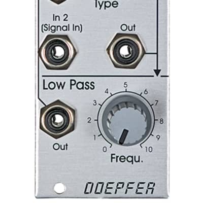 Doepfer A-196
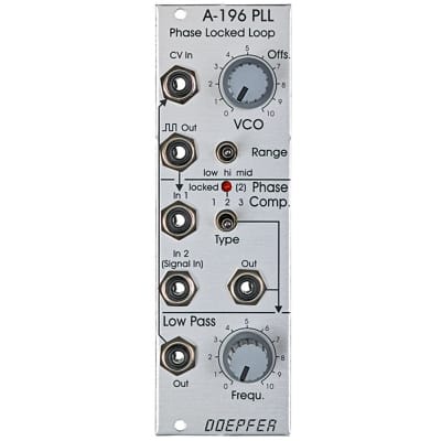 Doepfer A-196 PLL
 Doepfer A-196 PLL
 Doepfer Doepfer A-196 Phase Locked Loop