
Module is available as a DIY project only.
This Module is currently available.
 Specs are approved by the manufacturer
Sequential switch
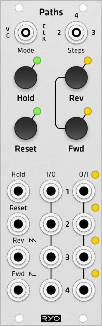
A 4:4 cycling sequential switch, featuring simultaneous forward/reverse stepping, hold, reset, and an additional voltage controlled mode based on the same design as our VC Sequencer. Also on board are push buttons for each function enabling you to play and perform the switching with a more human input.
This sequential switch will do all your standard 1>2, 1>3, 1>4 or the other way around with great real-time as well as external voltage controllability.
But its when you start playing around with multiple sources and destinations that things start getting fun and weird! You could for instance shuffle around four different trigger patterns to trigger four different percussive generators for interesting variations, or why not 4 oscillators shuffling between 4 different destinations, panned and processed in various ways?
Whatever your sequential switch application might be, we're confident the Paths is up to the task!
Just like the VC Sequencer it is clockable by very high clock rates (100 kHz tested) and CVable with full audio range. All for your experimental waveshaping duties.
Clock Mode
When clocking with FWD clock input or button the sequence will advance one step forward. When clocking with REV clock input or button the sequence will advance one step in reverse.
If a clock comes in exactly at the same time on both inputs the forward will have priority over the reverse.
CV Mode
In CV mode there is two CV inputs. The one that shares the reverse clock input is full wave rectified and the one that shares the forward clock input is half wave rectified. It uses an active rectifier without voltage drop or a dead zone around 0V.
The half wave rectified (FWD) with one bump on the rectifier symbol, will clip any signal below 0V and above 5V. The difference to the full wave rectified input (REV) with two bumps on the rectifier symbol, is that it will turn any negative volt into positive as well. So -1V is the same as +1V and -5V is the same as +5V etc.
Switch routing
When I/O1 is connected to O/I1, I/O2 is connected to O/I2 and so on.
When I/O1 is connected to O/I2, I/O2 is connected to O/I3 and so on, and I/O4 is connected to O/I1.
When I/O1 is connected to O/I3, I/O2 is connected to O/I4 and I/O3 is connected to O/I1 and so on.
Routing explanation image:
http://ljunggrenaudio.com/products/PATHS/pathsrouting.png
Additional information, schematic and front/side/rear photo links
http://ljunggrenaudio.com/products/switches.html
http://ljunggrenaudio.com/paths.pdf
http://ljunggrenaudio.com/products/PATHS/paths.jpg
11 Users are observing this


These merchants probably sell this module. Huh?
