
This Module is currently available.
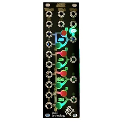
AONX is a combined boolean logic device by kNoB technology
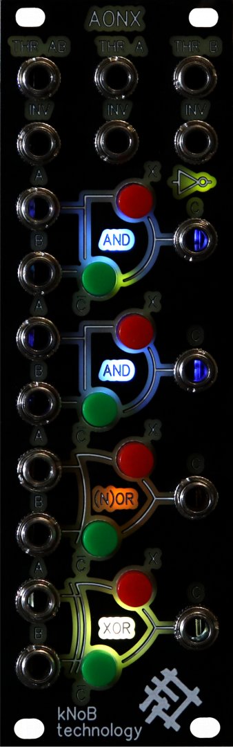
AONX is a combined boolean logic device, consisting of logical elements (N)AND (N)AND (N)OR X(N)OR and NOT (analog), as well as a small passive signal splitter, where each logic gate compares the voltages at its inputs and gives at the output the result of a mathematical equation, corresponding to the type of logical element. The device is designed so, that the signal can be sent to all inputs on the AB, A, and B lines, or separately, the device independently connects certain signal paths, depending on which connectors are used at a given time.
Technical specifications
All inputs can receive voltages from -5V to + 10V, inversion is available over the entire input voltage range.
Logic inputs can receive voltages of 0 - + 5V, voltages above + 5V, and are limited by a protection mechanism up to 5.1V.
THR connectors are passively interconnected.
The INV connectors are passively interconnected.
The logic gates accept input and output voltages as logic levels high (1) and low (0). If the input voltage is lower than 2.5V, then it is read as a low level (0), if the input voltage is higher than 2.5V, then it is read as a high level (1).
The outputs of the logic gates can only have voltages of 0V at low state or 5V at high state.
Tables of functional states of logic elements, depending on the input levels at their inputs, are shown in the image below in the module structure.
The output of each logic element can be turned off (MUTE) and inverted (¯с), with this you can change the function of the original logic elements:
AND -> NOT INV = NAND
OR -> NOT INV = NOR
XOR -> NOT INV = XNOR
this way you can get all the variations of binary logic gates
Example: signal 1 goes to all inputs of logic elements through the THR AB connector, signal 2 is applied to input B of the (N)OR element, respectively, below the input B of the X(N)OR element there will also be signal 2, and signal 1 will be on these elements only at the A (N)OR inputs, and A X(N)OR.
Internal connections save the number of wires required in connectors to form a working patch.
User manual PDF link - https://vk.cc/cd4714
| Date | Region | Description | Price | Seller |
|---|---|---|---|---|
| USA | Fully tested, perfect working condition. Minimal rack rash.About Used It... | $131.00 |
4 Users are observing this


 kNoB technology AONX - Complex boolean
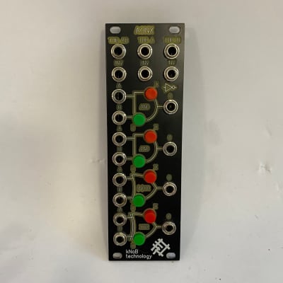 kNoB technology AONX