
This Module is currently available.
Five Input Majority Logic Module
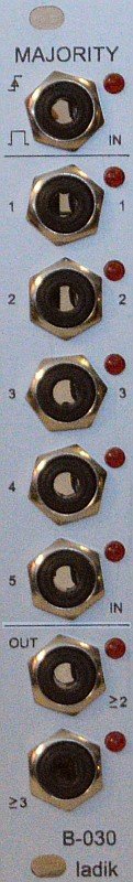
From top:
clock/trig/gate input
5 logic inputs (left labeling) / 3 logic inputs (right labeling)
min. “2 out of 3” output
min. “3 out of 5” output
There are five logic inputs. If nothing is plugged into an input, then it defaults to ‘false’. When three or more inputs (a majority) are ‘true’ (active, positive) then the >_3 output is ‘true’. Otherwise, that output is ‘false’. When two or more of the inputs 1-3 are ‘true’ then the >_2 output is ‘true’. Otherwise, that output is false. Thus, if you connect up just three of the inputs, the >_2 output will signal a majority of the connected inputs. If more than three inputs are connected, then it just signals that at least two of them are ‘true’. The >_2 and >_3 outputs can be used at the same time and can, with further logic, be used to detect ‘exactly two’, for example. Note that, if only two inputs are connected, then the >_2 output
corresponds to AND. Likewise, if only three inputs are connected, then the >_3 output corresponds to AND.
Processing can be set to “realtime/gated” or “triggered” using internal jumper (top jumper). Most top jack (clock/trig/gate input) is normalled to ‘true’ thus if nothing is plugged into this input “realtime” processing is allowed when top jumper is set. If an gate signal is plugged into this input processing is allowed only when input gate is active (‘false’ gate freezes outputs). If internal top jumper is removed then processing is allowed only at moment of rising edge of incomming clock/trig/gate (“triggered”).
Internal bottom jumper set makes normal output logic, jumper removed makes inversion of both outputs (in other words outputs will become to
2 Users are observing this

