
This Module is currently available.
Semi-Random Trigger Pattern Generator
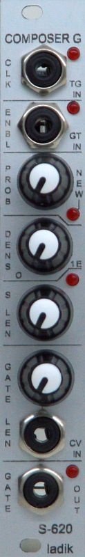
S-620 Composer G (gates) module for Eurorack / Doepfer A100 system.
From the top down:
CLK: Clock input jack (trigger) + LED
ENBL: Enable input jack (gate) + LED
PROB: Probability of new note being generated knob + new note generated indicator LED
DENS: Gate Density or Odd/Even Beat Probability knob (jumper selectable)
S LEN: Sequence Length knob + LED
GATE LEN: Gate Length knob + CV input jack
GATE: Gate Output jack + LED
The S-620 Composer G is a trigger pattern generator with up to 32 steps that creates semi-random patterns of gates. A new trigger or gate at the Clock input jack (CLK) steps through the pattern. Patch a clock or LFO signal to the CLK input to determine the overall tempo.
You can control the probability of when new “trigger” events (Gate Output = on) and “rests” (Gate Output = off) are randomly generated. The Enable input decides when there is a probability of this happening. It defaults to On (enabled), which can be overridden with an external gate signal; its status is confirmed by an LED. If the Enable input is On for the next step in a pattern, the S-620 then looks at the value of the Probability knob to determine whether or not a new trigger or rest will actually be generated. If you always want new triggers or rests to be randomly generated when the Enable input is On, then set Probability to full clockwise. To keep the current pattern, either send 0 volts to Enable, or turn Probability full counter-clockwise. If its Probability LED is on, then a new trigger or rest is being randomly generated. If this new event is different than the old event for the current step in the sequence, the LED will be at full brightness; if the LED is dimmed, the new event – a trigger or a rest – is the same as the old event for the current step. If the LED is off during a step, Probability decided not to randomize the event fo this step.
In the top right corner of the S-620’s circuit board are two jumpers. If the jumper on the left is installed (the default), the Probability knob works as described above. If the left jumper is removed, the Probability knob changes function to weight the probability of generating a trigger event on an even step number versus an odd step number.
The Density knob weights the probability of whether a trigger event (gate on) or rest (gate off) will be generated for the next new event. Turning Density full clockwise causes the S-620 to attempt to generate a trigger event for every step of the sequence; turning it full counter-clockwise causes the S-620 to try to generate a rest for each step. Set it to its middle position (12:00) for an even chance whether a trigger or rest will be generated.
The Sequence Length knob is used to set the length of the repeating pattern: 1, 2, 3, 4, 6, 8, 12, 16, 24 or 32 steps. Its LED turns on if you have selected a length that is a “power of 2” (2, 4, 8, 16, or 32) steps long.
Gate length can be set using either the GATE LEN knob, or an external CV. If a patch cable is plugged into the CV jack, the knob becomes an attenuator for that voltage.
As mentioned above, on the top right corner of the S-620’s circuit board are two jumpers. If the jumper on the right is installed (the default), Gate Length works as described above. If the right jumper is removed, the S-620 looks ahead to the whether the next step is a trigger or a rest; if the next step is also a trigger event, the gate will stay high, creating a musical “tie” between those steps.
20 Users are observing this

