
Module is available as a DIY project only.
No info about availability.
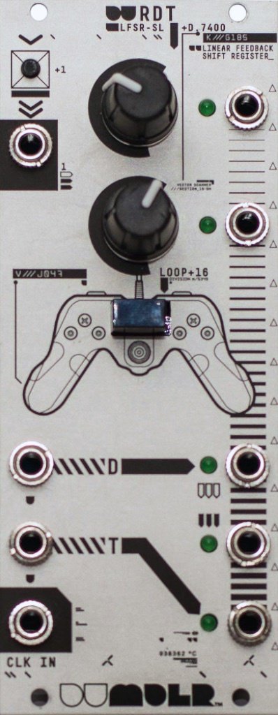
16-bit sampling Linear Feedback Shift Register (LFSR) logic sequencer
The Detroit Underground DU-RDT is a synthesizer module for the Eurorack format with a Swiss army knife of sequential logic functions on a common clock input: a 16-bit sampling shift register which operates as a 16-bit LFSR when the input is disconnected, with two selectable outputs from the top and bottom bytes as well as a pattern lock switch; a D-type flip flop with normal and complemented outputs; and a T-type flip flop normaled to the D-type’s complemented output. A variety of useful and interesting trigger and gate patterns are possible with creative use of the inputs and outputs.
This is at its core just a sequential logic utility for generating, manipulating, and delaying gate/trigger patterns on a common clock. We believe in modules being modular; what the module does is really up to how you use it.
So, how can you use it? You can think of the module as having two "sections" whose outputs change only with the clock input. All inputs are clock/gate/trigger inputs (no CV).
The top section is a 16-bit shift register (the R in RDT), which means that each time a clock pulse comes in, whatever is in that register gets kicked down the line, and after 16 clocks it falls off the end. The knobs select which of the 16 bits go to each output - you can pick bits 1 through 8 for the top output, and 9 through 16 for the bottom output. This gives you two selectable delays on the input. If you don't connect an input, the register acts as a linear feedback shift register, which is basically a random pattern generator -- and you can feed pulses into it using the little button over the input, sort of like the write switch on the Turing Machine. Both outputs will still output the same pattern, with a variable amount of delay (in clocks) between them. The black pushbutton switch locks the current pattern of the register -- you can still change the delay via the knobs while the pattern is locked, but the input jack/button and LFSR have no effect.
The bottom section is a pair of flip flops, D-type and T-type, respectively (the D and T in RDT). The D flip flop output simply replicates on each clock pulse whatever its input was on the last clock pulse -- a one-clock delay, or a 1-bit register if you will. There is also an inverted (always opposite) output of the D flip flop. The T flip flop toggles when the input is high (gate active) on a clock pulse, otherwise it retains its on or off state. When nothing is connected to the inputs, the outputs basically act as /2 and /4 clock dividers, respectively.
This is all implemented using monolithic logic ICs that can easily run at audio rates if you feed an audio signal to the clock. The most interesting result would probably be the LFSR (audio-rate LFSR noise sources through an envelope are used to create various sounds, e.g. snare drums).
(The following links are outdated:)
Operations Manual
http://detroitunderground.net/dumdlr/du-rdt-manual.pdf
Build manual
http://logick.ca/du-rdt-build-manual
DIY kit $119.
9 Users are observing this


These merchants probably sell this module. Huh?
