
Module is available as a DIY project only.
This Module is discontinued.
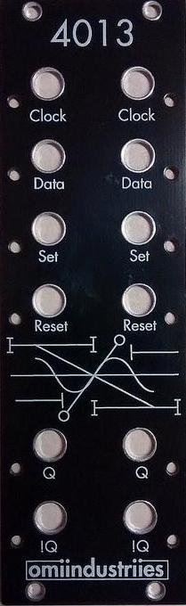
The 4013 is Dual Digital Data Storage (Dual Flip-Flop) in eurorack format!
A little info on the 4013 series digital logic IC:
"The 4013 device consists of two identical, independent data-type flip-flops. Each flip-flop has independent data, set, reset, and clock inputs and Q and Q outputs. These devices can be used for shift register applications, and, by connecting Q output to the data input, for counter and toggle applications. The logic level present at the D input is transferred to the Q output during the positive-going transition of the clock pulse. Setting or resetting is independent of the clock and is accomplished by a high level on the set or reset line, respectively"
From the designer (via muffwiggler):
well I will try to give some examples. it is a bit like a swiss army knife. as much as maths can be used 26 different ways. it is definitely one of those endless modules. but anyway I will try to explain. it is a data storage module. much like a sample & hold module is storing a voltage sampled from the input. the input gets sampled when a rising edge is applied to the clock input. how this differs from the traditional sample & hold is simple. we force all input voltages above or below 1v into a binary logic state HIGH or LOW that is stored in the 1 bit register digitally. that data will be present on the output indefinitely until it has changed states. the output Q has with it an included, non-modular, binary logic inverting output. this would be pretty boring except we have 3 ways to load data. only 1 of those ways requires both clock and data pins to be operated simultaneously. the other 2 inputs are each dedicated 1 wire non-synchronous control+data inputs. a rising edge sent to SET forces Q to be HIGH without waiting for a clock input. the output Q stays high until a rising edge is applied to either the clock or reset pins. any consecutive gates or triggers sent to SET after it has already been SET are redundant they have no change at Q. RESET is similar to SET however the Q is forced LOW when a rising edge is applied to RESET. it will stay that way till a rising edge is applied to CLOCK or SET. obviously, when SET or RESET are used, the output will only change if SET or RESET represent a logic state that is different from the logic state currently held at Q.
this is just the basic operation of the 4 input pins. this does not even begin to discuss applications for modular synth patches. as you can see, there are many rules the 4013 must follow to make mathematical logical operations. in addition to the 4013 logical operations, there are 4 analog voltage comparators that perform hybrid analog+binary front end to binary only interface. these also have rules. for example if input > 1v then this pin = HIGH. so many rules!
APPLICATIONS
before I discuss possible audio processing applications, I will present applications that process, generate, delay, quantize (timing), or divide triggers and/or gates sent in different combinations to the 4 input pins. the most basic function of a 4013 is realized when the quarter note clock (master tempo) is patched to the clock input. the S + R lines are not patched or intentionally patched with logic LOW. in this mode all gates will only change state with the clock. this output Q can then be used to control other events in the modular that require musical timing. however the module will perform the same task under the same rules when in is clocked by anything that is not musical or consistent in timing. the most powerful feature of the 4013 is combing synchronous and non synchronous control signals. this allows the user to make improvisational timing superimposed with the clock or alternatively, change freely between synchronous (clocked) and non-synchronous (not clocked) at will. sending an arcade button to SET and a button to RESET creates a binary user interface on two buttons that can be operated without visual feedback of Q logic state. this can be useful for controlling mutes, sequential switches, sequencers (run, stop), or binary mode selector CV inputs on other modules that lack buttons. 4013 can be used as a clock divider but it can also be used as a sub oscillator. the same patch can be used for both. if an arcade button is patched to the clock divider patch, the 4013 converts the momentary action of the button to the latching two state action of a toggle switch. when audio signals are patched to 3 or 4 inputs, shit gets crazy. the sampling affect creates aliasing. the forced bits create glitches. the 4013 has a priority when both SET and RESET go HIGH at the same time. whatever the preference, it will be the exact same preference all the time on all units.
so to sum up everything. the 4013 works great with arcade buttons, works great with making random timing less random. works great for making glitchy pulses from pretty regular oscillators. it can be a suboscillator, it can be a clocked comparator. it can remember things (1 bit storage) until it is powered off. this can offer new self generating patches that were not possible before the modular gained the ability to store information from anywhere and apply it to anything. without memory, a modular can only process signals while signals are present. the 4013 allows the modular synthesizer to autonomously create new timed events based on rules that have been pre-programmed by the user. the machine not only thinks, it remembers.
5 Users are observing this

