
Module is available as a DIY project only.
This Module is currently available.
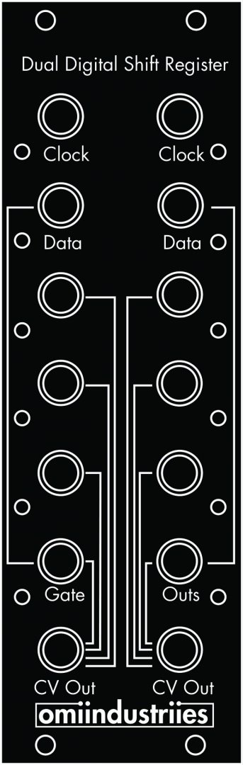
DIY version of the Dual Digital Shift Register
This is the first DIY version of the Dual Digital Shift Register
The outputs on this version are +/-5v
The Dual Digital Shift Register is a cmos shift register based pseudo-random cv and gate generator. It uses two 4 bit shift registers and a digital to analog converter to create aleatoric sequences. A shift register has two inputs a clock input and a data input which expect binary signals ie gates or square waves, off or on. When the clock goes high the shift register looks at the data input and if it is also high it puts a high signal into the first stage of the shift register, if it is low the first stage is low. On the next clock pulse whatever is in the first stage is moved to the second stage and the second stage is moved to the third stage, etc. and the shift register looks at the data input and moves that data into the first stage. When a bit reaches the 4th it is fed back into the data input and is xor'd with the incoming data signal. This means that when either one of the inputs are high the data is high but when they're both high at the same time the data is low. The 4 bit are also fed into a digital to analog converter which takes the 4 bit binary signals and converts them into a voltage.The digital to analog converter (DAC) uses the inverse of the bits to create the cv output, so all bits at 0 outputs the highest voltage, about +5 volts, and all bits at 1 means the lowest voltage, about -5 volts. In a 4 bit shift register the possible number of states is 16 (2^4).. You have leds to indicate the state of each stage whether high or low. You also have gate outputs for each of the stages, which go from -5 volts to +5 volts
The outputs are determined by the relationship between the clock and data inputs. Using closely related signals you will get patterns that loop, such as outputs from a clock divider. Using signals that aren’t as related to each other will create more random seeming patterns. A way to create even more chaotic sequences is to route feedback into the patch. Patch the cv output of the ddsr into a cv in on the signal for the clock or data oscillator to make a feedback loop. Attenuators are suggested to dial in the amount of feedback.. Attenuators or attenuverters are generally recommended with the ddsr.
Build documentation: http://www.eatyourguitar.com/DDSRBOMV1.pdf
3 Users are observing this


These merchants probably sell this module. Huh?
