
Available as an assembled Module and as a DIY project.
This Module is currently available.
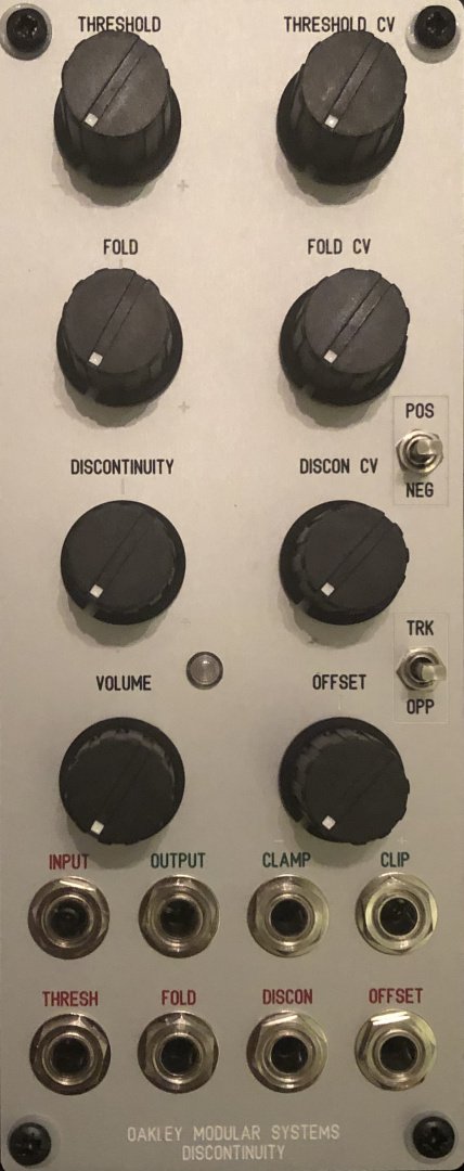
Waveshaper, Wavefolder, Clipper, Ring Modulator & Wavesplicer
The Oakley Discontinuity is an updated version of the Oakley Wavefolder. Like its predecessor the Discontinuity is a voltage controlled waveshaper module that uses the same core technology as the old Oakley Wavefolder. But it is different enough in circuitry, usage and possibilities to be introduced as a new module. The new discontinuity and offset controls and CV inputs make this module very unique. It is capable of creating some very beautiful tones out of simple VCO waveforms. All can be varied dynamically in musically interesting ways. And input waveform type, whether triangle, sawtooth or sine, can have profound tonal differences in the Discontinuity's output. Varying the input level can also have some amazing effects.
Internally the module is arranged in five sections that are connected in series:
The Soft Clipper
This circuit gently restricts all input signals to around +/- 5.5 volts peak. It essentially mimics an overdriven valve or tube amplifier.
The Clamper
This circuit prevents the output from going above or below a preset limit, called the threshold. Unlike the soft clipper circuit the clamping is hard and abrupt. And unlike the soft clipper the limit is completely voltage controllable. The threshold can be controlled with the Threshold knob or input CV. A three way toggle switch offers three modes of clamping:
a. POS
The input signal is clamped when it exceeds the threshold voltage, e.g. if the threshold voltage is set at 2V, then all parts of the input signal that rise above 2V will be clamped.
b. NEG
The input signal is clamped when it falls below the inverse of the threshold voltage, e.g. if the threshold voltage is set at 2V, then all parts of the input signal that drop below -2V will be clamped.
c. MIDDLE
With the switch in the middle position both negative and positive clamping is applied, e.g. if the threshold voltage is set at 2V, then all parts of the input signal that rise above 2V or drop below -2V are clamped.
The output level during clamping can be varied dynamically. This can be done either as a function of the threshold voltage by the Discontinuity knob and its CV input, or as a fixed offset with the Offset control and its CV input. Furthermore, the offset can either be applied symmetrically or asymmetrically depending on the Track/Oppose switch. It allows to actually remove any proportion of the original signal at the point where it exceeds the threshold voltages and replace it with another input. In other words we can splice one waveform in place of another. This has the potential to make some very new and wonderful timbres. As well as being passed on to the next stage of the module, the result of the Clamper is available at its own output.
The Clipper
What the Clamper bites off, the Clipper returns. The Clipper output is the part of the original input signal that gets chopped off by the Clamper circuit. So if you put a 5V peak triangle waveform into the Clamper, set the threshold to be 2.5V and set the mode switch to BOTH, the Clamper output will give you the neatly clipped trapezoid wave output, while the Clipper will give you the tips of the pointed bits of the original triangle waveform.
The Folder
The Discontinuity's fourth section is based around a four quadrant multiplier or ring modulator. Here the Clamper and Clipper outputs are mixed together. However, the Clipper output may be added or subtracted from the Clamper signal. The Folder knob and an external CV set the mix ratio and polarity. Again, consider the 5V triangle waveform with the polarity switch set to either POS or NEG. With the Fold pot set to 0, you get the plain Clamped signal at the main output. Turn the Fold pot clockwise and the clipped signal will return to create the original signal once more. But keep turning it, and the clipped signal is now bigger then the original. Now turn the pot the other way. The clipped signal gets subtracted from the clamped signal. You can get full wave rectification, thus your triangle becomes another triangle at twice the frequency. Multiplication. Turn it up further and more harmonics come in.
The Amp
The last stage is a simple x10 amplifier. The Discontinuity can clip accurately down to small levels if you want, so you need a good amplifier to bring it up to a decent level again.
Do not forget the Discontinuity will work with any signal, audio and CV. You can mangle EG outputs, LFOs and, of course, your VCO. Different waveforms will be treated in very different ways.
Video demonstration
The video below demonstrates the possibilities of chopping up a triangle wave input with a variety of manual and LFO tweaking.


These merchants probably sell this module. Huh?
