
This Module is a prototype or in a concept phase.
Dual multimode filter
(Superbooth 2024)
Module A-121s is a special dual multimode filter which can be used for parallel or serial organized dual mono filters. Even stereo applications are imaginable. The filter are based on two special circuits: one with highpass and bandpass outputs, the other with lowpass and bandpass outputs. It's a new filter design that is not used so far in any other A-100 filter module.
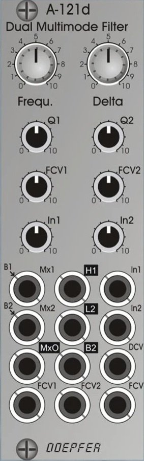
We attached great importance to the usability of the manual controls and CV inputs for dual filter applications: for the filter frequencies of both filters a common control (Frequ.) and a difference control (Delta, filter spread) are available. For both parameters even CV inputs are available (FCV, DCV). The resonance (Q1, Q2), the sensitivity of the individual frequency control input (FCV1, FCV2) and the level of the audio input (In1, In2) are adjusted by means of the individual controls for each filter.
The module has a simple audio mixing unit available with the inputs Mx1 and Mx2, and the output MxO. Provided that the mixer inputs are open bandpass 1 and bandpass 2 are normalled to the sockets Mx1 and Mx2. All other filter types are realized by connecting the other filter outputs (H1 = highpass 1, L2 = lowpass 2) to the mixer inputs. For details please refer to the sketches below that show all possible filter types.
Controls:
Frequ.: master frequency control for both filters

Delta: controls the difference between the frequencies of the two filters manually (frequency spread), at center position the frequencies are about the same

Q1 / Q2: resonance controls for filter 1 and 2

FCV1 / FCV2: attenuators for the individual frequency control inputs FCV1 (filter 1) and FCV2 (filter 2)

In 1 / In 2: attenuators for the audio inputs of filter 1 and 2
Sockets:
Mx1 / Mx2: audio inputs of the mixer, Mx1 is normalled to bandpass 1 (B1), Mx2 is normalled to bandpass 2 (B2)

MxO: audio output of the mixer

In1 / In2: audio input of filter 1 and 2  (In2 is normalled to In1)

H1: highpass output filter 1

L2: lowpass output filter 2

B2: bandpass output filter 2

DCV: control voltage input for frequency spread (Delta)

FCV1 / FCV2: individual frequency control inputs, processed by the attenuators FCV1 and FCV2, socket FCV2 is normalled to socket FCV1

FCV: common frequency control input for both filters (~ 1V/oct)
Triangle symbols indicate the normalling of sockets (B1>Mx1, B2>Mx2, In1>In2, FCV>FCV2). The four outputs are inverse labelled.
Technical note:
Ex factory the module is adjusted so that the resonance of the two filters does not reach self-oscillation. If desired the filters can be modified by the user by means of two trimming potentiometers so that self-oscillation is possible.
1 Users are observing this

