
This Module is currently available.
Chaotic Balls
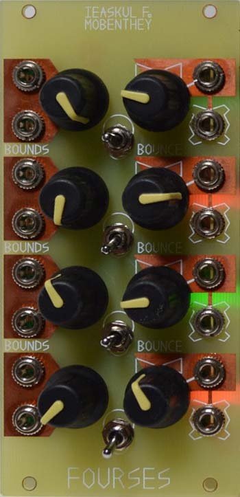
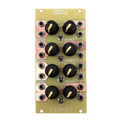
The Fourses module consists of four bounds/bounce oscillators, stacked on top of each other so that their bounds are mutual. Imagine four bouncy balls in a greased perspex tube only wide enough to permit them to travel along it. They bounce off of each other in the tube, and generate intricate but inter-related chaotic outputs. Each bouncy ball has the requisite basis and attenuverter knobs, and bounds inserts, control input, and triangular output.
Fourses is a 12HP Eurorack module that runs on +12 and -12 volts. Attach power connector positive to “+” and negative to “-”. Failure to follow proper power polarity will result in instant destruction of unit.
Looking at the front panel of Fourses, note that inputs are marked by copper fill. The four operators are exactly the same in appearance. The bounds of any operator are dictated by the ones immediately above and below, except for the very top and bottom operators; the top upper bound is set to eight volts, and the bottom lower bound to negative eight volts. The bounds of any operator, however, have inserts that you can use to manually set a boundary to whatever voltage you wish. This may introduce Ieaskul's masthead, the paradox wave, that comes about when a lower bound is greater than an upper bound, causing the oscillator to go into hyper oscillation since it cannot rest in any stable zone.
Connected to the bounds inserts area, there is a rate knob that acts in a special, Fourses-like way: knob in middle causes the up- and down- slopes to be equally fast, and the operator will bounce easily; turn the knob clockwise and it will have a very slow down-slope and a fast up-slope, counter-clockwise is the opposite. The philosophical reasons for such a knob came about when testing the original fourses; control of slope symmetry is just as important as, or perhaps more important than, control of frequency in Fourses. The control input, with associated attenuverter also controls frequency and symmetry in the same way. An attenuverter works like this: at noon the modulations are nulled out, they have no effect; clockwise from there they increase in intensity, with positive input meaning “more”; to the counter-clockwise direction, modulations increase as well, but with negative input meaning “more”. This knob is essential to controlling how much, and in which direction, your modulations apply. The “position out” can hardly be called “triangle out” anymore, but it is the same electronically as would a triangle output- a reading of the current position of each bouncy ball.
For each operator there is a range switch. When in middle position, the operator runs at a standard audio rate. Pointing downward is a low audio rate, and pointing upwards is a definite CV, lowest rate.
56 Users are observing this


These merchants probably sell this module. Huh?

 Ieaskul F. Mobenthey Fourses Quad Bound
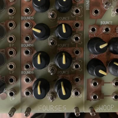 Ieaskul F. Mobenthey Fourses