

No info about availability.
Dual Timer/Gate Extractor
It isn’t fancy but is meant to create timing events which can be put to use elsewhere in your system.
Controls & Connections
Pushbutton for top channel.
Pulse length for top channel. Trigger pulse to @3sec.
This switch selects whether channel one responds to the leading edge of a signal applied to it or the entire length of the signal. When in the first position the output will be determined solely by the length control (B). When in the second position the output will be either the length of signal sent to it or the length defined by the length control (B) - whichever is longer. NOTE: the two channels will not oscillate if the switch is in the second position.
Input for top channel. This is logically OR’d with the pushbutton. As this (and the input to the lower section) is a comparator based,any signal that passes the circuit signal can be used as an input. So that could be an LFO, VCO, noise circuit or anything else you can think of.
Output for the top channel.
This switch controls whether the output of the lower channel is fed back to the input of the top channel. When activated and the output of the lower channel is high it inhibits the top channel. When switch (C) is to the left and the input of the top channel is held high (by either the pushbutton or a gate) the two channels will oscillate with the rate determined by the two length controls.
Pulse length for bottom channel. Again, trigger pulse to @3sec.
Input for lower channel. With nothing inserted this is normalled to the output of the top channel.
Output of the lower channel.
Two independent trigger or fixed length gate extractors.
With the lower channel feeding back into the upper channel it can be used to generate a stream of pulses whenever a gate (or the button) holds the input of the upper section high.
Again with the lower channel feeding the upper section which is being used to extract trigger pulses from an input, this can be interrupted by the the lower section to create breaks in the stream.
Send a stream of trigger pulses to the input of the upper section and also to an OR gate. Also send the output of the lower section to the OR gate. Feed the output of the OR gate to an envelope and use it to create closed/open hi-hat style rhythms.
Using the push button on the upper section to create either fixed length triggers and gates or with the switch in the second position a gate for as long as the button is held.
Use the two sections as a trigger delay.
Feed the two outputs to a DC mixer and then send the output of the mixer to the exponential FM input of an oscillator.
Use the module to divide down a faster clock stream.
https://docs.google.com/document/d/1SQlQwoxdF0rtVh-MioFgtS_dJlfpMBeBvsLTyhuJoc0/edit


 Scott Mckeon SM Fuzz
 Behringer X32 40-Input 25-Bus Digital
 Ashdown MAG 300H EVOIII
 Fender CME Exclusive Player Jazzmaster
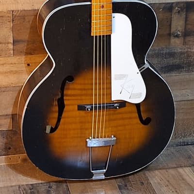 Kay Jumbo Archtop
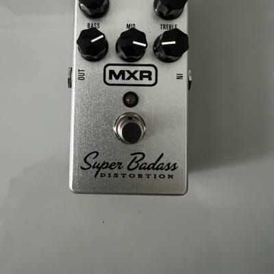 MXR Super Badass