Melakarta
- Dimensions
- 16 HP
- 22 mm deep
- Current Draw
- 20 mA +12V
- 5 mA -12V
- 0 mA 5V
- Price
- $208
Available as an assembled Module and as a DIY project.
This Module is currently available.
MG ID: 47700
Up/down clockable, binary-addressable carnatic transposer/sequencer
The idea for this module came from my friend Rodrigo Kendrick. He liked DAC but was a bit burned out on western tonal structures, and had recently missed out on an electronic lehra machine in a facebook marketplace deal which fell through. These machines are a kind of practice tool for carnatic musicians that plays a wide variety of different raga. Think that "casio auto-chord" function on old casio keyboards, but for carnatic music.
Unwilling to wait for another one to come up on the used market, he did some cursory research, and sent me an early-morning design document, expanding the functionality of DAC with a scheme of two rotary switches and one toggle switch to select the pitch sets for all 72 Melakarta ragas and specified a clock input that would run up and down the selected raga in ascending then descending order, with the ability to turn around or reset on command. In theory this would allow the complex rhythmic and sequence rules of the raga to be implemented with external logic and sequencers, but still give the module enough sequencing functionality to explore the pitch sets of these raga on it's own.
I got excited and went a bit silly 'helping' until we had shoehorned in a pile of other features like binary addressability of the selected swara (interval), gate outputs for each swara, an 'inhibit' input that mutes the transposition voltage while the clock continues in the background, CV controlled halving of the clock frequency, extra +1oct input, and the logic-inverting toggle switches from the DAC on several inputs.
This design is all analogue using discrete MOSFETs and 0.1% tolerance resistors in a volt per octave weighted DAC driven by a 4000-series CMOS based sequencer.
Yes, it might have been simpler to use a microcontroller.
16hp +12V: 20mA -12V: 5mA
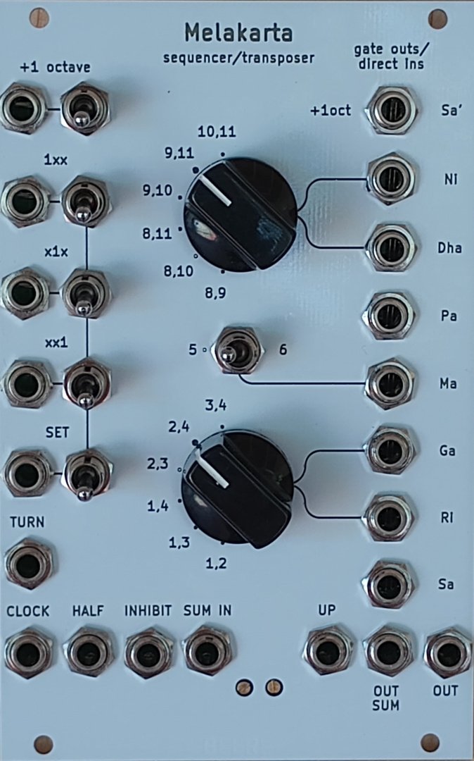
The two rotary switches and the toggle switch in the middle of the panel together program which swaras/intervals will be stacked up to form one of 72 possible combinations.
You could think of raga like scales. In fact several of the Melakarta ragas are analogous to western scales!
For example: Śankarābharaṇam is the equivalent of the western major scale and can be selected on this module by setting the front panel switches to 2,4, 5, 9,11.
There is no voltage control over the position of these switches. If you want to change key mid performance you'll have to reach in and do it yourself :)
OUT (bottom-right) is the main CV output and is a 1V/octave equal-tempered control voltage corresponding to the current position on the raga/scale and the state of the additional octave up input/switch.
SUM OUT is the same voltage summed with whatever signal you insert into SUM IN. This is used for transposing up the CV from another sequencer/keyboard etc.
The two main modes of operation are best described as 'clocked' and 'addressed' modes.
In clocked mode the output climbs sequentially up the raga on each rising edge applied to CLOCK until it reaches the top and turns around and heads back to the Ṣaḍjam/root (0 volts) and turns around to go up again.
This up and down march can be interrupted/modified by applying a gate or positive CV to the TURN or HALF inputs.
A gate or positive CV on TURN reverses the direction of the next clock movement.
A gate or positive CV on HALF divides the clock frequency by 2 (ignores every second pulse).
UP is a gate output with LED indication of which direction the output will go on the next clock pulse.
Addressed mode is enabled by the SET input/toggle switch.
In this state clock pulses will be ignored and the selected swara depends on the 3-bit binary inputs.
With nothing plugged into the SET input the toggle switch next to it can be used to manually engage addressed mode.
SET sw up = addressed
SET sw down = clocked
Patching a gate or positive CV into the SET jack also enables addressed mode.
In this case the toggle switch decides what to do with incoming CV/gates:
UP = gated (module is in addressed mode as long as SET is high)
DOWN = momentary (transfers the binary inputs to output only on the rising edge of the signal on SET)
With the toggle switch DOWN the SET input behaves sort of like a sample and hold. When given a gate the output jumps to the current decoded binary value and stays there until another rising edge on SET, or another rising edge on CLOCK moves the output up or down by one.
The three binary inputs are xx1, x1x, 1xx. Together they form a three-bit binary word that is decoded into one of the 8 swara/intervals on the selected raga/scale.
Like the SET input, with nothing patched into the binary inputs the toggle switches manually set each bit when in addressed mode.
For example the panchama (Pa) can be programmed by setting 1xx up and the other two down. Or, with all switches down and nothing patched to the binary inputs, SET can function as a reset to zero. (or any position on the scale you like programmed by the switches)
Also like the SET input, patching a gate or positive CV to the binary input will set that bit high with the switch down, and set it low with the switch up. Playing around with the switches can give quite different melodic results from the same CV/inputs!
The +1 octave input adds 1V to the output regardless of clocked or addressed mode and its toggle switch behaves like the binary address switches.
With nothing patched the switch manually adds +1 octave of CV, with a gate/positive CV applied to +1 octave input the logic of the input is inverted with switch up.
“+1oct” lights up near the top right jack to show when the extra octave is being applied.
The INHIBIT input 'mutes' the output voltage while a gate/positive CV is applied.
The state of the counter, clocking, and SET functions still continue 'in the background' so when the INHIBIT signal is removed you might not be on the same note you left. +1 octave is not affected and will still work when INHIBIT is active.
GATE OUTS are provided for each interval in the scale and go high when their swara is active.
secret bonus feature
The GATE OUTS are tapped from the control signal that activates the FETs that switch the individual intervals on and off and will also accept inputs without hurting anything. Feeding a strong (approx. +5V) gate signal into an interval's gate out will force that interval on regardless of the current count and that interval will be summed with whatever other intervals are active. This trick will quite likely result in notes outside your selected raga/scale being played. Also, forcing an interval on that is already selected by 'normal' operation will do nothing. It won't become any more 'on' than it already was.
This bonus feature isn't affected by INHIBIT.
There's absolutely nothing stopping you from ignoring all but the rightmost 4HP of this module and using it to make nonsensical melody CV with whatever signals you care to shove up the gate outs.
CALIBRATION:
The left trimmer on the panel should be adjusted first.
With nothing patched in to any input and all toggle switches on the left hand side UP adjust the left trimmer until exactly 2 volts (to as many decimal places as you have the capability/can be bothered) is present on OUT.
Once you've done that patch OUT into SUM IN (without changing anything!) and adjust the right trimmer until exactly 4 volts is present on OUT SUM.
If the intervals sound out of tune with your VCO you can always tweak a little by ear if you prefer.
https://isaacbeers.square.site/product/melakarta-transposer-sequencer/15
Marketplace sell and buy used modules
| Date | Region | Description | Price | Seller |
|---|---|---|---|---|
| EU | The overall condition of this freshly built module is p... | €170,00 | KitKatAndy | |
| EU | BLACK or WHITE panel - freshly built, with love paypal... | €170,00 | RTFM |
5 Users are observing this
Right Now on eBay

USA

These merchants probably sell this module. Huh?