

This Module is currently available.
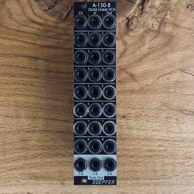
Octal linear VCA vintage edition
Module A-130-8 contains eight linear voltage controlled amplifiers (VCAs). Each VCA features a control voltage input (CV), a signal input (In) and a signal output (Out). In addition three mixers are included: the socket labelled "1-4" outputs the sum of the VCAs 1-4, the socket labelled "5-8" outputs the sum of the VCAs 5-8, the socket labelled "1-8" outputs the sum of all eight VCAs.
The signal inputs are able to process levels up to about 20Vpp without clipping (20Vpp = 20V peak-to-peak or about -10V...+10V) . Each CV input is equipped with a trimming potentiometer that is used to adjust the sensitivity of the CV input in question. In the factory the module is adjusted for the CV range 0...+5V but can be re-adjusted by the user for other control voltage ranges (e.g. 0...+10V).
The amplification range for each single VCA is 0...1. The signals of the sum outputs have a lower amplification to avoid distortion at the sum outputs.
The VCAs and mixers are fully DC coupled, i.e. the module can be used for the processing of both audio and control voltage signals. The control voltage and signal inputs can be normalled by means of small solder pads (e.g. 1 > 2 > 3 > 4 and so on, or 1 > 5, 2 > 6, 3 > 7, 4 > 8 for the stereo application mentioned below).
Typical applications
any kind of VCA application (e.g. voltage controlled attenuation of audio or control voltage signals)
two voltage controlled mixers with four channels each
voltage controlled stereo mixer with four channels each, for this the control voltage inputs have to be correspondingly patched or internally normalled: CV1=CV5 /CV 2=CV6 / CV3=CV7 / CV4=CV8
voltage controlled mixer with eight channels
add-on for the Joystick module A-174-4
Technical notes
The following document shows the positions and functions of the jumpers and trimming potentiometers of the module: A130_8_trimming_potentiometers_and_jumpers.pdf
When the trimming potentiometer in question is moved CCW (counterclockwise) the sensitivity of the CV input in question increases (view to the top edge of the module).
Trimming procedure: apply the max. CV voltage that will occur in your application (e.g. +8V) to the CV input and a constant audio signal to the audio input (e.g. a VCO sawtooth). Then adjust the trimming potentiometer in question until the max. output level is reached and does not become higher even if the trimming potentiometer is turned further. Possible the the trimming potentiometer has to be turned back again a bit to find the correct position.
With the trimming potentiometer adjusted to max. sensitivity the linear amplification starts at about +0.1 control voltage (CV). We introduced this small dead range of about 100 mV to make sure that the VCA fully closes with CV = 0V.
It's possible to change the amplifications of the internal mixers used for the sum outputs (1-4, 1-8, 5-8) also to 1. Pay attention that then clipping/distortion may occur at the sum outputs. For this the 22k resistors R41 (Sum 1-4), R44 (Sum 5-8) und R51 (Sum 1-8) have to be replaced by 47k. As they are smd resistors sufficient experience with soldering/desoldering of smd parts is essential. And we have to point out that warranty is void if such modifications are carried out by the customer. The positions of the resistors are shown in the document A130_8_trimming_potentiometers_and_jumpers.pdf.
13 Users are observing this


These merchants probably sell this module. Huh?

 Doepfer A-130-8v Octal Linear VCA
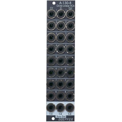 Doepfer a-130-8v
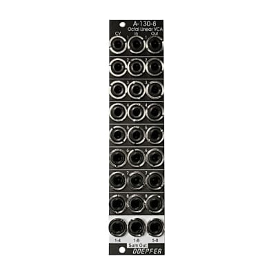 Doepfer A-130-8v
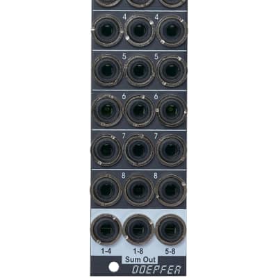 Doepfer A-130-8v