
Available as an assembled Module and as a DIY project.
This Module is currently available.
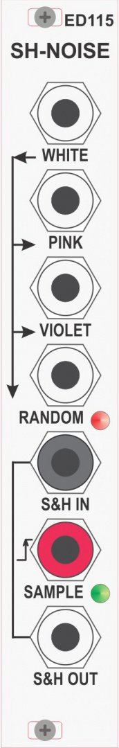
Noise Generator / Sample & Hold Module
The ED115 comprises a Noise Generator and a Sample & Hold.
NOISE GENERATOR
The Noise Generator generates a WHITE noise output which is also fed in to a series of filters to generate a PINK output a VIOLET output and a RANDOM output.
WHITE Noise
The White Noise generator operation is based on the noise generated by the Zener breakdown phenomenon in a BJT inversely polarized base-collector junction. In other words, such shot noise involves the statistical fluctuations of the current flow present in the bipolar transistor.
The generator makes use of a common 2N2907 biased by a constant current source. To increase the amount of shot noise attainable, the collector of the 2N2907 is left open and the base-emitter is reverse-biased. That is, the BJT is connected as a zener diode to exploit the reverse breakdown phenomenon. With this configuration, the reverse breakdown voltage exhibited by the emitter-base junction can be easily observed using an ordinary spectrum analyser. The attainable bandwidth is about 300MHz, and the power output is about -70 dBm. This signal is passed through an amplifier which sets the output voltage at a nominal 8V peak-peak.
PINK Noise
The PINK filter is a 3dB/octave filter which is pretty linear across the range 10Hz to 15kHz to within 1dB across the full 50dB range. A final stage buffer-amplifier sets the output level to around 8V peak-to-peak.
VIOLET Noise
The VIOLET filter has two frequency dependent elements in the feedback path. The first feedback element on its own would produce a 6dB/octave rise in the gain of the amplifier from 0dB at 0Hz via 3dB at 9Hz to 20dB at 90Hz. The second feedback element on its own would produce a 6dB/octave fall in gain from 0Hz to 1kHz above which the gain would remain constant at 0dB.
The combined effect of these feedback elements is that below 90Hz the 6dB/ocatve rise and 6dB/octave fall cancel out, giving a gain of 20dB. Above 90Hz the gain falls at 6dB/octave to 0dB at 1kHz, above which it remains constant. The result being that the bass end of the noise spectrum is boosted, and is available at the VIOLET output. A final stage buffer-amplifier sets the output level to around 8V peak-to-peak.
RANDOM Noise
The RANDOM noise output is a low-pass 2nd-order Sallen-Key filter which passes only the very low frequency components to produce an extremely low frequency `random voltage'. Fluctuations of the random voltage are displayed on a LED indicator which will change from RED to GREEN as the output switches above and below 0V.
SAMPLE & HOLD
The Sample & Hold section is derived from that used in the ED109 – TGTSH from Ian Fritz and takes an instantaneous sample of the input signal and presents it to the OUT output. The resultant output is a `random voltage' that changes on each positive edge of the SAMPLE input which is indicated by the ‘SAMPLE’ LED.
The SAMPLE connector is normalised to the RANDOM output of the NOISE section while the IN connector is normalised to the WHITE noise output. Inserting a jack in to any of these connectors will allow an external signal to be used instead
| Date | Region | Description | Price | Seller |
|---|---|---|---|---|
| USA | Some rack rash. Works perfectly, I now have other noise/S&H solution... | $70.00 |
6 Users are observing this
 Elby Designs ED115 SH NOISE$134.41


These merchants probably sell this module. Huh?
