This Module is discontinued.
High bandwidth voltage-controlled signal crossfading, voltage-controlled amplifier, video switching, signal multiplication, luma keying, chroma keying, masking, wipe generation, amplitude classification, window comparison, voltage-controlled pulse delay
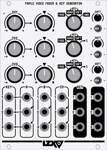
Triple Video Fader & Key Generator is a high bandwidth signal processing module which includes three voltage-controlled crossfaders, three high-speed voltage comparators, and three control voltage processors. Switched jacks, control source selection switches and internal AND logic allow these circuits to interact in a versatile number of complex operational modes.
FADER
Voltage-controlled crossfader with two inputs and one output. When control source is at 0 Volt, channel A is completely on. When control source is at 1 Volt, channel B is completely on. Voltage levels between 0 Volt and 1 Volt represent a proportional mix of channels A & B. With signal inserted to channel B only, the fader behaves as a traditional voltage-controlled amplifier.
KEY GENERATOR
High speed voltage comparator serving as a key generation source. When the key generator input is greater than the voltage represented by the sum of the CV input and bias controls, the key output is 1 Volt (on). Otherwise, the output is 0 Volt (off). Inversion switches select between non-inverted and inverted versions of this logic signal.
CONTROL SOURCE
Control voltage (CV) inputs are processed by level and inversion controls and then summed with a variable 0 to 1 Volt bias. This sum serves as the threshold level for the key henerator, and as the control source for the fader while in FADE mode.
PATCHING TECHNIQUES
Single Threshold Comparator
Insert a signal into any key input. Associated 0 to 1 Volt bias control determines the voltage threshold for the key signal appearing at the associated key output. Key inversion toggle switch can select positive or negative logic. In positive mode, key output will be 1 Volt when the Key signal is higher than the threshold level. In negative mode, key output will be 1 Volt when the Key signal is lower than the threshold level. Another signal can be inserted to the associated Control Voltage (CV) input, and the associated level and inversion control adjusts the amount the external signal adds to the keying threshold.
Multiplier/VCA (voltage controlled amplifier)
Insert any signal into B input of a fader channel. Switch associated fader control source switch to FADE. Amplitude of the input signal is then controlled by the sum of the 0 to 1 Volt bias control and any signal input to the CV input. This can be used to multiply two video signals together, or as an automated fader.
Automated Crossfading
Insert any two signals into A & B inputs of a fader channel. Switch associated fader control source switch to FADE. Associated 0 to 1 Volt bias control determines the proportional mix between A & B inputs appearing at the fader output. When bias control is at 0 Volts, channel A will be 100% amplitude, with channel B at 0%. When bias control is at 1 Volt, the opposite is true. Another input signal can be inserted to the associated Control Voltage (CV) input, and the associated level and inversion control adjusts the amount this signal adds to the bias. In this way, a low frequency modulation signal can be used to smoothly fade between the two signals.
Luma Keying
Patch up the single threshold comparator patch as described above, but take the output from fader output instead of key output. Insert the input signal to A channel input (which will be automatically be connected to the associated Key input.) Switch the associated fader control source mode switch to KEY. Now the input signal will be keyed in and out based on its own brightness level. A second signal can be inserted to “B” channel to switch between two sources.
RGB Fader
This patch uses all three channels to fade between two RGB signals. Configure the automated crossfading patch as described above, sending red, green & blue signals to A & B inputs of all three channels. Switch channels 2 & 3 to ->1 mode in order to select channel 1 as the master control source. Chanel 1?s CV & Bias controls will now identically control crossfading between all faders.
Window Comparator
This patch uses two channels together in order to generate a single key or switched signal with an upper and lower threshold. First, patch up the luma keying patch as described above, and patch the fader output of this patch to the key input of a second channel’s key input. Switch key inversion toggles on either channel to opposite positions and adjust key thresholds appropriately. Bias controls and CV inputs can modulate upper and lower thresholds separately. Additional note: If desired, the patch can be expanded to control “width” and “position” instead of upper and lower thresholds by using a third channel as a VCA to control the gain of the incoming modulation signal, which can then be applied equally to the two upper and lower thresholds.
Chroma Keying
Set up RGB fading patch as described above, but switch channel 1 to AND mode. Boas controls, key inversions and CV inputs on all three channels now determine the amount each color of channel A contributes to the Chroma key switching logic. With time spent finding the desired settings, any specific range of color can be targeted as the key source in variable degrees.
3-Band Amplitude Classifier
An amplitude classifier splits an input signal into different amplitude ranges and is useful for colorizer patches where you want control over the shared points between multiple bands rather than independently variable comparators. This patch uses all three channels. Switch all channels to Key mode. Switch channels 1 & 2 to -Key, and channel 3 to +Key. Insert signal source to A1 jack. Patch Key1 Out to Key2 In. Patch Key3 Out to CV2 In. Turn CV2 control fully counter-clockwise. Turn channel 2 bias control fully clockwise. Ensure that Bias1 is higher than Bias3. Now fader outs and key outs represent three split amplitude bands, with channels 1 & 2 controls and CV inputs representing the threshold points between bands 1 & 2, and bands 2 & 3.
Cascaded Crossfaders
Since each of the there CV crossfaders can function independently, they can be used to create several types of voltage-controlled signal mixes. One method is to take the outputs of crossfaders 1 & 2 and send them to the A & B inputs of crossfader 3. Up to four signals can be input to crossfaders 1 & 2 inputs, and crossfader 3 is used to crossfade between the outputs of the first two.
Max/Min Selector
This patch compares two input signals, and outputs whichever one is highest (max) or lowest (min) at that point in time. It can be replicated on all 3 channels to work on two triple colorspace (RGB) signals, or cascaded to multiple channels to add additional signals to the max/min selection. Input signal #1 to A input (which gets automatically connected to corresponding Key input). Input signal #2 to B input, and use a mult or stacking cable to send this same signal to corresponding CV input. Set CV control fully CW. Set bias control fully CCW. Set channel mode to “Key”. Positive logic selects “Min” response, negative logic selects “Max” response. Fader output jack represents the Max/Min selection.
Voltage Controlled Panner
A panner allows variable gain of 1 input signal to 2 separate outputs (as opposed to a crossfader, which allows variable gain of 2 input signals to 1 output.) This patch uses two channels of the TVF&KG. Input signal to B1 input (it will consequently be connected via switched jack to B2 input). Input CV source to CV1 input (which will consequently be connected via switched jack ot CV2 input.) Turn CV1 fully CW. Turn Bias 1 fully CCW. Turn CV2 fully CCW. Turn Bias 2 fully CW. Input signal will be panned between fader outputs #1 and #2 based on the external control voltage source.
https://www.lzxindustries.net/products/triple-video-fader-key-generator/
8 Users are observing this

