
No info about availability.
Eight-step sequencer for CV, trigger and gate signals
OVERVIEW
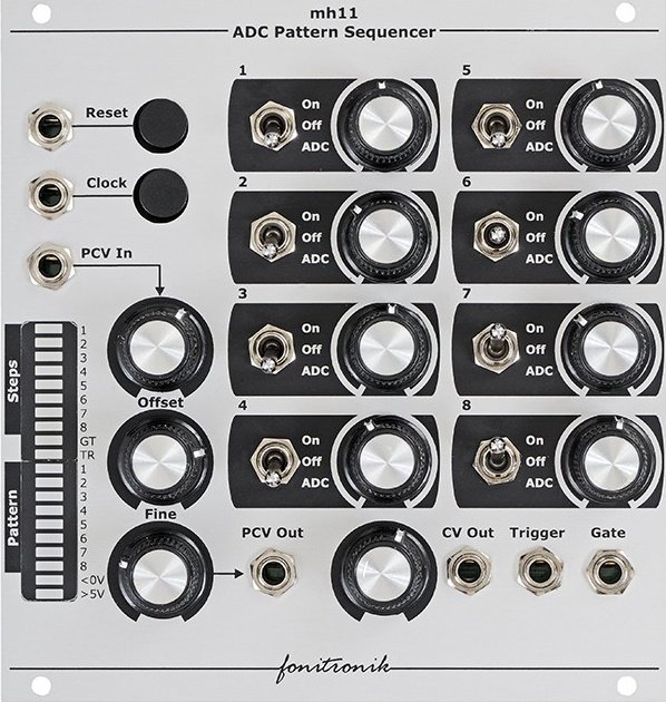
The mh11 ADC Pattern Sequencer is an eight-step sequencer for CV, trigger and gate signals. So far it´s like you would expect it to be... BUT:
The rhythmicity of the sequencer can be controlled by the ADC section in an interesting way. The ON / OFF state of each step can be set manually or it can be determined by a value ( 1 or 0) that is decoded by the ADC´s pattern. Sounds complicated but it´s just unusual. See the description below.
DETAILS
The pulse width of the clock signal at the input determines the gate length of the according step so it makes sense to use e.g. a LFO with pulse width control. The mh11 sequencer can accept clock signals up to audio range making it a graphic oscillator as well. An input for resetting the sequencer back to the first step is available as well. The clock button skips manually to the next step; the reset button resets the sequencer manually.
Besides gates with variable length the sequencer can output triggers at a separate socket.
Now to the ADC section: Each step has a three-position switch which determines if the step is played or muted. In third position a value from the ADC (analog-digital converter) determines if the step is on or off. The ADC converts a 0-5V voltage at the P-CV input into one of 256 possible binary 8-Bit patterns. Each Bit is equivalent to a step of the sequencer and can be either on (1) or off (0). This will produce an sequence like 00101101. The according step set to "ADC" will then read out either a "1" or "0", and thus will be either played or muted. Changing or scaling the input voltage will change the sequence of 1s and 0s and will create nice variations of the rhythmical pattern.
!!!!!
The ADC doest´t like voltages above 5V so use the attenautor and offset control to adjust the input voltage. The current active step and the current state of the 8 bits are displayed with two LED bars.
!!!!!
CONNECTORS
ADC: Processor CV (P CV) input and P CV output
sequencer: CV output, trigger output, gate output, Reset input, Clock input
manuel : http://www.fonitronik.de/manuals/mh11-QuickStart-e.pdf
6 Users are observing this


These merchants probably sell this module. Huh?
