Model 39
- Dimensions
- 4 HP
- Current Draw
- 20 mA +12V
- ? mA -12V
- ? mA 5V
- Price
- $100
This Module is discontinued.
MG ID: 1343
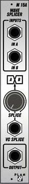
wavesplicer
The Model 39 Wave Splicer, part of the mighty ELF series, is a Plan B original design which merges waveshapes - on the waveform level - to produce complex timbres not possible through standard mixing.
The M39 senses the zero-crossing of Input A and and transitions to Input B when a Splice command occurs, the timing of which may be set by either a pot or an external voltage control. The M39 is phase-consistant to the A input, meaning the output will return to A signal at the next zero-crossing, regardless of period length. This allows the user to sculpt a number of unique phase-variable waveforms from a single VCO (sine/tri, sine/saw, sine/square, tri/saw, tri/square and saw/square), the ratio of each parent waveform determined by the location of the splice. Imagine a waveform which is three-quarters saw and one quarter square which retains the ability to apply PWM to the last third and/or change the phase relationship (the ratio) of the two in real time.
The upside of doing it as a module as opposed to a feature built within a VCO is it allows wave morphing from mutliple sources, not just the phase-locked signals from a single source. You can morph from a sub-octave generator, or an external audio source, to noise, or of course from two independent VCOs set to either harmonic or non harmonic relation to one another.
Processing of two independent phase-locked square waves (via the parent VCO's sync input) , allows for dedicated PWM of the + and - sub-cycles. Not only can the on-time of the positive-going peak and negative-going trough be varied independently, but by introducing a VC into the M39's splice point the mixture (or combined on-times) or the two can be modulated as well, allowing for three levels of PWM in a single waveform (see audio examples).
How is works
The M39 has with two inputs: A and B. On the positive transition of the A, the output is automatically switched to pass that signal alone. The user however determines when (and if) the output shifts to the B input. Using only the manual control, turning the SPLICE pot fully CCW will yeild only the A signal. Turning it fully CW returns only the B output. However it's in the settings between these two extremes where things get interesting as the Wave Splicer shifts between the two waveforms to create a single, period-cosistant timbre morphed from the combination of the two signals it's processing.
By introducing a voltage control, the M39 shifts it's splice point in realtime by tracking the voltage level of the VC. Imagine a waveform built from the square and saw components of a single VCO in which a timbre can be morphed by two levels of PWM, one controlling the on-time of the square source and the other controling the mix between the two inputs.
Please note: Becase the M39 actually passes each signal to a single output, distribution of the two in relation to the SPLICE pot setting is dependant on the amplitude levels of the two parent signals being processed.
Marketplace sell and buy used modules
13 Users are observing this
Right Now on eBay

USA


These merchants probably sell this module. Huh?